Hello dear Grasshopper user. Thank you for your interest in EndPoints plugin. The EndPoints plugin was
developed for the
purpose of importing alignment and digital terrain model (DTM) into Rhino/Grasshopper from (Land)XML
files and export your building/bridge/tunnel or other
to IFC file format. The imported elements (alignment and DTM) are intended to serve as initial input for
design of various infrastructure parts
(e.g. bridges, tunnels, rail and road structure).The purpose of IFC exporter is to provide users with an
easy-to-use but sufficiently comprehensive option for producing IFC
files directly from Rhino/Grasshopper. However, how the plugin is utilized is entirely up to the user.
IFC schema describes the built
environment, including buildings and civil infrastructure. It is an open international standard
(ISO 16739-1:2018). Schema is vendor-neutral and
has the potential to be used across wide range of devices and software platforms. IFC schema has
many different use cases. IFC schema specification is the primary technical deliverable of buildingSMART International to fulfill its
goal to promote openBIM®. So far three versions are official (IFC 2x3, IFC 4
and IFC 4.3).
License and pricing
Export to IFC is based on xbim library (xbim toolkit, license), for which I am very grateful to the
creators of the xbim toolkit library. License and pricing policy for EndPoints plugin can be read here.
Version
Version: 1.4.4
Developed for Rhino 6 and higher.
Orientation in plugin
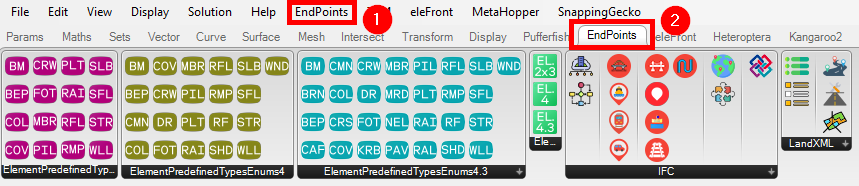
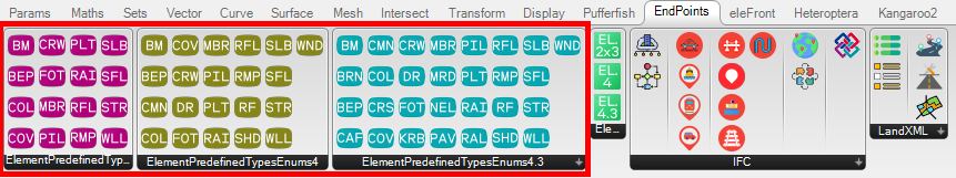
With the installation of the EndPoints plugin two new features will appear in the Grasshopper.
New tab in the top menu bar (1) with the plugin settings and new tab in the ribbon
menu (2) with plugin components.
Coordinate system and units
Grasshopper is unitless and units depend on the actual unit system set in Rhino. However, IFC is not (SI
units are always used). Automatic unit conversion is not included into IFC export engine.
As the main part of IFC is graphical data and its dimensions depend on Rhino unit system, only the length
unit matters. Ifc length units depends on the actual Rhinoceros units.
If the Rhino length units are set to one of the following units:
Meters
Centimeters
Millimeters
Microns
Nanometers
Kilometers
Megameters
Decimeters
Dekameters
Ifc length unit will be set according to Rhinoceros units. If not, IFCExport will produce a warning
message and Ifc unit will be set to meters.
Coordinate system can be defined in Ifc with IfcCoordinateReferenceSystem (for IFC 4.3). However, geometry
is always exported as it is located in Rhino. Coordination between different structures
is key in civil engineering and not all disciplines work in global coordinate system, the origin point and
rotation from X axis can be defined for IFC export.
Export to IFC
IFC is very complex and wide-purpose schema. It is not possible to cover all possibilities offered by IFC
schemas. The main purpose of EndPoints plugin is to simplify IFC production directly from Rhino/Grasshopper.
The exporter is focused on creation of IFC files, which should be used for coordination and delivery both
geometry and non-graphical data. In some cases export options may be limited. For successful export, rules
described in Input data structure rules section
must be followed. As different clients, companies and countries develop their own standards proper sorting
of data before export and how to get data inside Grasshopper is up to the user.
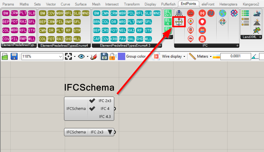
IFCSchema component
IFCSchema component is simple value picker parameter with predefined implemented IFC schemas. IFC
schemas 2x3, 4 and 4.3 are implemented.
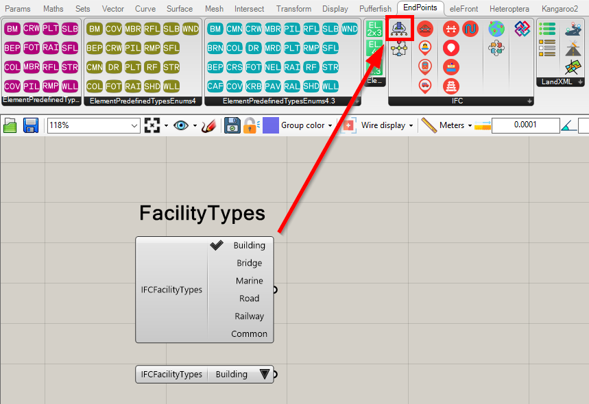
IFCFacilityTypes components
IFCFacilityTypes components are set of simple value picker parameters with predefined IFC
Facility types and its sub-types. These value pickers are valid only for export to IFC4.3 schema. For
IFC2x3 and IFC4, building is always used. Since IFC4.3 schema not building but facilities are exported.
Facility can be six different types.
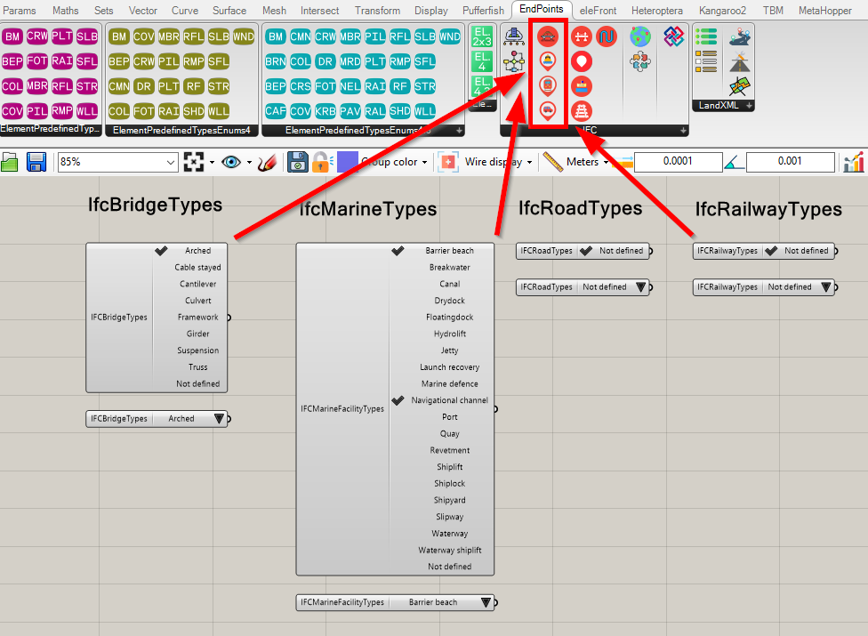
Each facility has its sub-types.
Facility sub-types values are enumeration defined by IFC schema, specifying further facility type. For
each facility new to IFC4.3 value picker with permitted values was created. Userdefined option
was removed as it was marked as wrong by buildingSmart validation
service.
IFCFacilityParts components are set of simple value picker parameters with predefined
FacilityParts. These value pickers are valid only for export facilities new to IFC4.3 schema. For
building export stories are always used as facility parts.
Each facility consists of different facility parts.
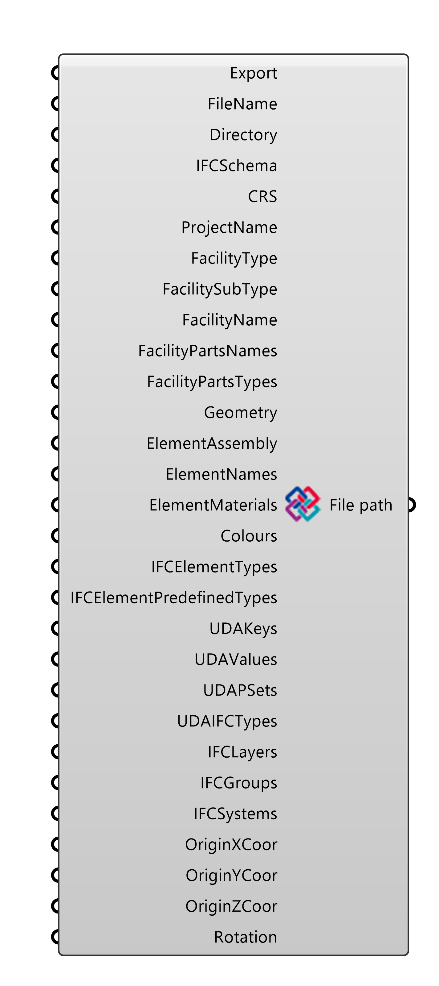
The component has multiple input parameters. The first parameter, Export, triggers the export if
all necessary inputs are provided and boolean true is input for this parameter.
The use of the native Button is assumed for Export parameter. FileName is the name
(without .ifc extension) of created IFC file. Directory is the path to the
directory where IFC file will be saved. IFCSchema input parameter is a string with the version of
IFC schema. The use of the EndPoint IFCSchema component is assumed for
IFCSchema parameter. Input CRS is inner class with coordinate system. This input is optional additional
and applicable only for IFC 4.3 schema. The use of the EndPoint IFCCRS component is assumed for
CRS input parameter. Input ProjectName is optional parameter. User can set name of a project.
Inputs FacilityType, FacilitySubTypeFacilityName are optional and specifies what type of
facility structure is, its name and sub-type. If IFC schema 2x3 or 4 is used, structure is always exported as
building. If FacilityType is building FacilitySubType is neglected automatically.
The optional parameters FacilityPartsNames and FacilityPartTypes are trees with the names
and types of all IfcFacilityParts classes which will be defined inside the IFC file. If input is not
provided, no parts are defined in the IFC file and all IfcBuildingElement/IfcBuiltElements classes are
part of the IfcFacility (IfcBuilding, IfcBridge, IfcMarineFacility, IfcRoad, IfcRailway) class. If tree
is provided,
then IfcBuildingElement/IfcBuiltElement classes are matched with the IfcFacilityPart according to tree
paths. If FacilityType is set to building or IFCSchema is 2x3 or 4,
FacilityPartType is neglected automatically (building storeys are used).
The parameter Geometry is a tree with all geometry which will be exported to IFC file. The
Geometry parameter takes only meshes, and each mesh is exported as single IfcBuildingElement. The
parameter ElementAssemblies
is a list with internal classes containing wrapped information about IfcElementAssembly classes. The use
of the IFCElementAssembly component is assumed to generate this input list,
and no additional information for this input is needed. IfcElementAssembly is created only if its
FacilityType match FacilityType required for IFCExport. Each class in the list will be exported as a
IfcElementAssembly class
with defined stories, IFC types, properties, layers and colours. However, both the Geometry and
ElementAssemblies inputs are optional, at least one must be present. Otherwise, a warning message
is shown, and IFC file is not created.
The ElementNames input parameter is optional. User can define name property of each element
exported into IFC file. Input ElementMaterials is optional. User can defined IfcMaterial property
of each exported element. The Colours parameter is optional and must be a tree with colours defined
as RGB (3 x integers in range 0 to 255). Tree structure must match Geometry tree structure. Each
mesh should have a defined colour. However, if number of defined colours in tree path is smaller than
number of meshes in same tree path, the last item in actual path is used as a colour
for missing colours. If the Colours input is not defined, then the default transparent color is
used for all elements.
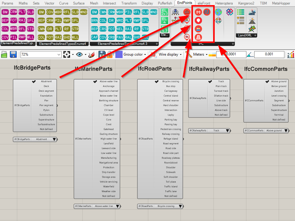
IFCElementTypes parameter is optional and must be a tree with strings (case-insensitive) defining
types if IfcBuildingElement. Tree structure must match the Geometry tree structure. Each geometry input
should have a defined IfcElementType. The default IfcBuildingElement set in the IFC
settings is used if IFCElementTypes input is not defined.
IFCElementPredefinedTypes input parameter is optional and must be a tree with strings (case-insensitive) defining
predefined types for each IfcElement. Predefined types are defined in IFC schema. Enumeration for each element type can be
defined with value pickers in the ElementPredefinedTypesEnums containers.
List of implemented IfcBuildingElements/IfcBuiltElements:
Optional parameters UDAKeys, UDAValues, UDAPSets are trees used for defining the
non-graphical information for each IfcBuildingElement. Structure of these trees must match each other
and correspond with the Geometry input tree structure. The ruling element is always
UDAKeys, which represent
names of the non-graphical attributes. According to the path and position inside the actual item of
UDAKeys, corresponding values of non-graphical attributes and property sets names are retrieved
from UDAValues and UDAPSets inputs. Default attribute value "Value_not_defined" and
property set name "Not_defined" are used if there is no item at the same position.
All non-graphical attributes are exported as IfcPropertySingleValue. The parameter UDAIFCTypes is
optional and can be used for the definition of IfcPropertySingleValue nominal value types for each
non-graphical attribute. Tree structure of strings (case-insensitive) must match the structure of
UDAKeys. IfcPropertySingleValue type set in the IFC settings is used if the
parameter is not defined.
List of implemented IfcPropertyValues nominal value types:
Note that even if all UDA values are inserted as strings, they must be convertible to the type regarding
the defined UDA Ifc type (e.g., if IfcReal is required, string must be convertible to a decimal number
etc.). If conversion is not possible, attribute is written in IFC file as IfcLabel, and warning message
is shown. Definition of units for non-graphical is not implemented and default
units, possibly derived from SI units, are used. The optional parameter IfcLayers is a tree with
names of layers in which elements will be placed. Each Geometry item is matched with layer
according to its path. If IfcLayers input is defined but not matched with Geometry item,
no layer is used. Input parameter IfcGroups is optional. Structure of input is tree with
names of group in which elements will be placed. Each Geometry item is matched with group
according to its path. Input parameter IfcSystems is optional. Structure of input is tree with
names of systems in which elements will be placed. Each Geometry item is matched with system
according to its path.
Optional parameters OriginXCoor, OriginYCoor and OriginZCoor can be used to define
vector between of Rhino's local coordinate system (in which geometry is defined) and Rhino's global
coordinate system (in which IFC file will be located, points measured, and coordinated).
The last parameter, Rotation, can be used to define angle between X axis of Rhino's local
coordinate system and Rhino's global coordinate system. A positive value is measured from Rhino's'
global X axis in the counterclockwise direction. The angle can be inserted in degrees or radians
according to a selected option in the IFC settings dialog.
Output parameter File path is a path to the created .IFC file.
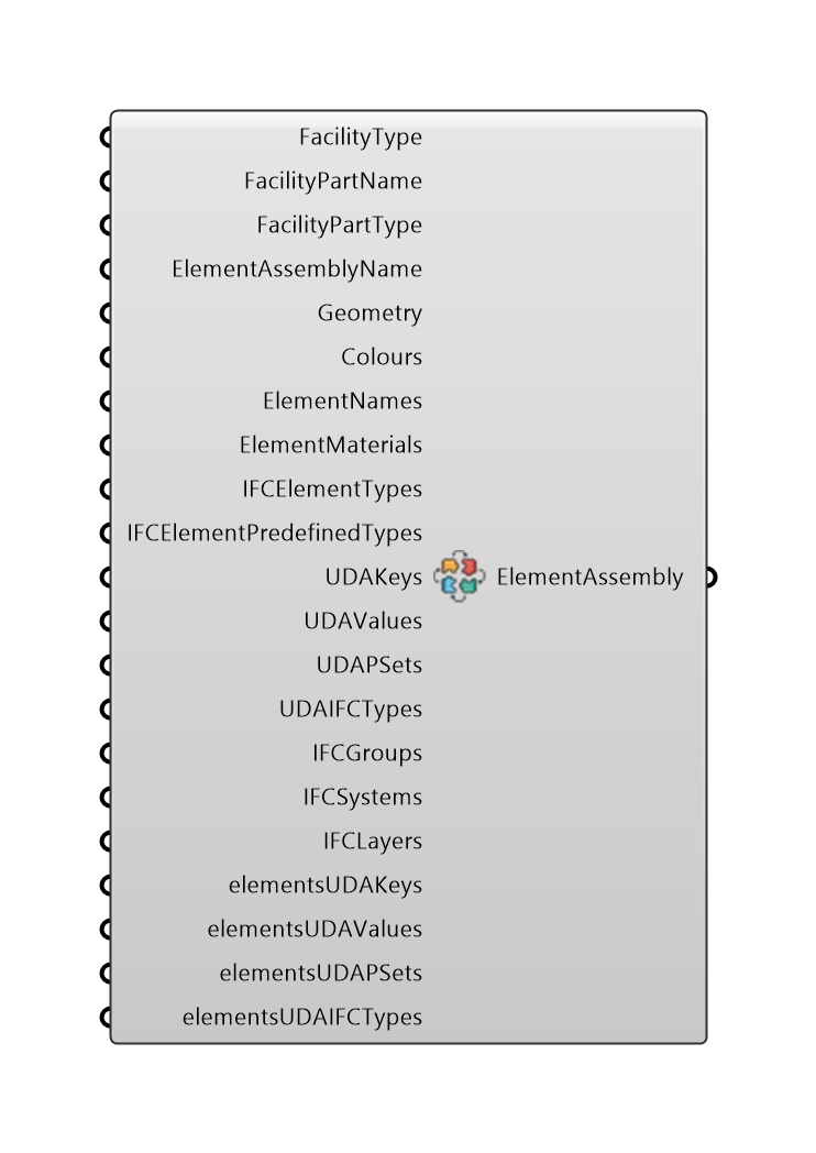
IFCElementAssembly component
The component has multiple input parameters which function in the same way as inputs for IFCExport component. However, there are few differences. If data for
IFCElementTypes is not provided, all members of each IfcElementAssembly are type of IfcMember.
The input Geometry is mandatory and not optional. All elements in each branch of the input tree
are grouped into one IfcElementAssembly. Each member in Element assembly has facility part and layer.
Color and IfcType can be set separately for each member of the element assembly. UDA properties are
set only for element assembly and not for each member. UDAs for each element in the assembly are matched to the element by the path
of the DataTree. UDA path must be one level deeper then Geometry input. Last index in the path must match position of the
element in the Geometry input.
Output parameter ElementAssemblies is a list of plugin internal classes with wrapped information
(facility type, facility part, geometry, layers, names colors, non-graphical information) about element
assembly and its elements. This output should be only inserted to input parameter ElementAssemblies of
IFCExport component.
IFCCRS component
Input parameter CRSName is a string with the name of CRS and correspond with
Name attribute of IfcCoordinateReferenceSystem.
Input parameter CRSDescription is string with the informal description of this coordinate reference system according to Description attribute of IfcCoordinateReferenceSystem.
Input parameter GeodeticDatum is string with name by which datum is identified according to GeodeticDatum attribute of IfcCoordinateReferenceSystem.
Output parameter CRS is a internal classes with wrapped information
about coordinate reference system. This output should be only inserted to input parameter CRS of
IFCExport component.
Input data structure rules
To export all data properly, it is necessary to follow rules for inputs tree data structures. These
rules are described in the following flowcharts. Generally, total length of paths of your branches does
not matter, but inputs have to have same path indices, and
some inputs have to have depth length one index longer or shorter. Only in this case are geometries with
proper attributes matched correctly.
IFCExport
IFCElementAssembly
IFC Settings
After clicking the IFC Settings button in top menu bar, the plugin IFC settings option dialog
appears. Here, you can set up different options for IFC export. Various export settings
can be also created and saved for future use.
The dialog consists of four tabs with various settings for IFC export. The top dropdown menu contains
predefined and saved profiles. If the user has not set any setting profiles, the default profile is always
used.
New profiles can be easily created and saved for further use. To apply settings or save/load/delete profile,
use the buttons at the bottom of the dialog.
Set: Apply current settings and keep the dialog open. These settings will be lost if Rhino is
closed.
Set and close: Apply current settings and close the dialog. These settings will be lost if Rhino
is closed.
Close: Close the dialog.
Load: Load saved settings according to selected profile in top dropdown menu.
Set and save: Apply current settings. These settings will be saved to a profile selected in top
dropdown menu. New profiles can be created if new profile name is provided. These profiles are kept even
if Rhino is closed.
Delete: Delete current selected profile from saved profiles.
In the General tab, following options are present:
Author name: Author name displayed in the file header.
Organization: Organization displayed in the file header.
Organization address: Organization address name displayed in the file header.
Authorization name: Authorization name displayed in the file header.
Authorization mailing address: Authorization mailing address displayed in the file header.
IFC facility part by path: If checked, the FacilityPartsNames input in IFCExport is
paired by structure path not by each element. See Input data structure rules
section.
Rotation in radians: If checked, the Rotation input in IFCExport is set to radians.
Otherwise, it is in degrees.
Parallel: If checked, multiple processors are used for IFC export import.*
Number of processors: The maximal number of processors allowed for parallel computing. Applied
only if parallel computing is allowed for IFC Export.**
*Parallel computing is used in specific parts of export. Using parallel computing may not lead to speed-up
export. See time result under the ExportIFC component.
**If a value is equal or smaller than 0, maximum number of processors is used.
In theIFC 2x3 tab, following options are present:
Default IFC Element type 2x3: Default IFCBuildingElement type can be selected. If the user does
not define IFCElementTypes input in IFCExport or IFCElementAssembly components, this value is used.
Default IFC UDA value type 2x3: Default IFCPropertySingleValue nominal value type can be
selected. If the user does not define UDAIFCTypes input in IFCExport
or IFCElementAssembly components, this value is used (if possible).
In IFC 4 tab, following options are present:
Default IFC Element type 4: Default IFCBuildingElement type can be selected. If the user does not
define IFCElementTypes input in IFCExport or IFCElementAssembly components, this value is used.
Default IFC UDA value type 4: Default IFCPropertySingleValue nominal value type can be selected.
If the user does not define UDAIFCTypes input in IFCExport or IFCElementAssembly components, this value is used (if possible).
Export as tessellation 4: Defines what geometry should be represented by tessellation
and what by brep.
Four options available.
In theIFC 4x3 tab, following options are present:
Default IFC Element type 4.3: Default IFCBuiltElement type can be selected. If the user does not
define IFCElementTypes input in IFCExport or IFCElementAssembly components, this value is used.
Default IFC UDA value type 4.3: Default IFCPropertySingleValue nominal value type can be
selected. If the user does not define UDAIFCTypes input in IFCExport
or IFCElementAssembly components, this value is used (if possible).
Export as tessellation 4.3: Defines what geometry should be represented by tessellation
and what by brep.
Four options available.
Default color 4.3: Default color can be selected. If the user does not define Colorsinput
in IFCExport or IFCElementAssembly components,
this value is used.
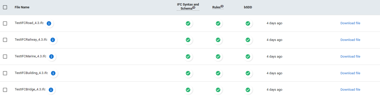
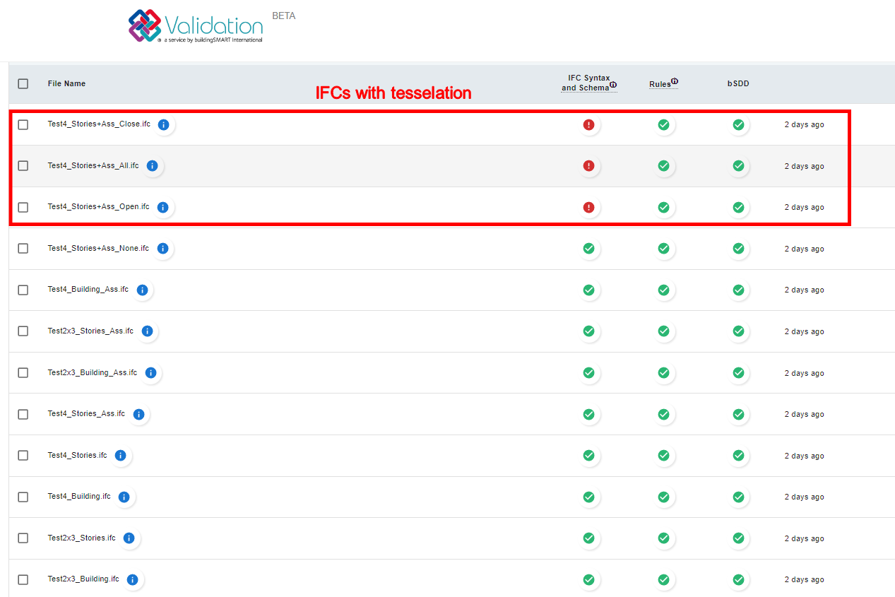
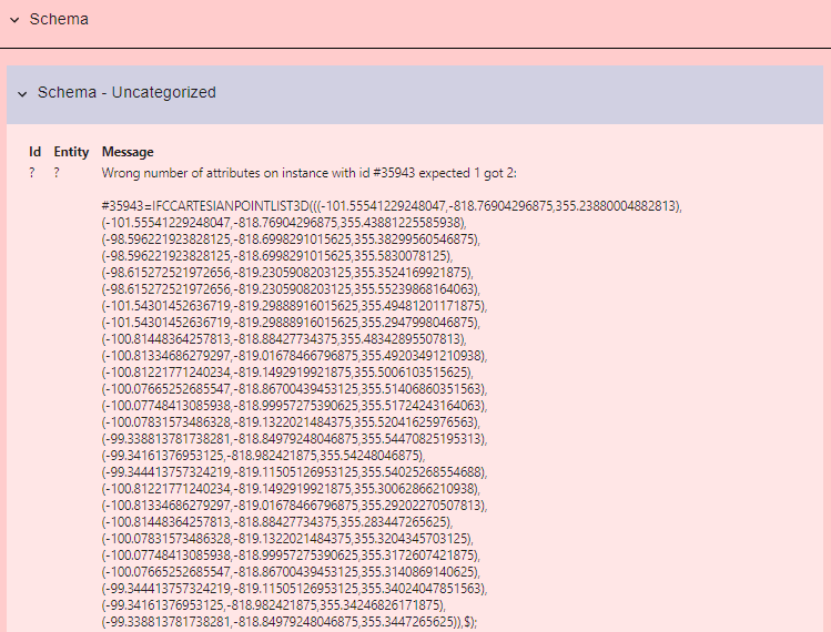
IFC validation
Correctness of exported IFC files was tested with buildingSMART International validation service.
All files are correctly written except in cases when geometry is written as tessellation. In this case
IfcCartesianPointList3D should have only one attribute but XBIM engine wrote two (possible in IFC
4x1 schema and higher). Tessellation error should not have impact on the IFC functionality, and
software capable of showing IFC should work correctly. Unfortunately, it is not in author's capacities to
perform enough tests to ensure all user exports will work absolutely smoothly. If you observe any errors
or inaccuracies, please contact the author.
Best practices
Always check the result and compare it with the original data.
Play with mesh topology for optimizing IFC export and mitigating huge IFC files.
(This should be solved in version 1.3.2 and higher) Always check the result of meshing. Rhino may
have problems with meshing geometry when it is at great distance from global origin. In this case, move
geometry near the global origin and define local origin point and rotation in IFCExport
component.
Some uncommon rules (national codes and rules) may not be taken into account in IFC export. Always check
the result.
Use tessellation for as many objects as possible, it will significantly speed up export.
If you are not sure about UDA Ifc type, IfcLabel will always work.